Data center cooling water piping
Robotic welding of 90° flanged elbows for data center cooling
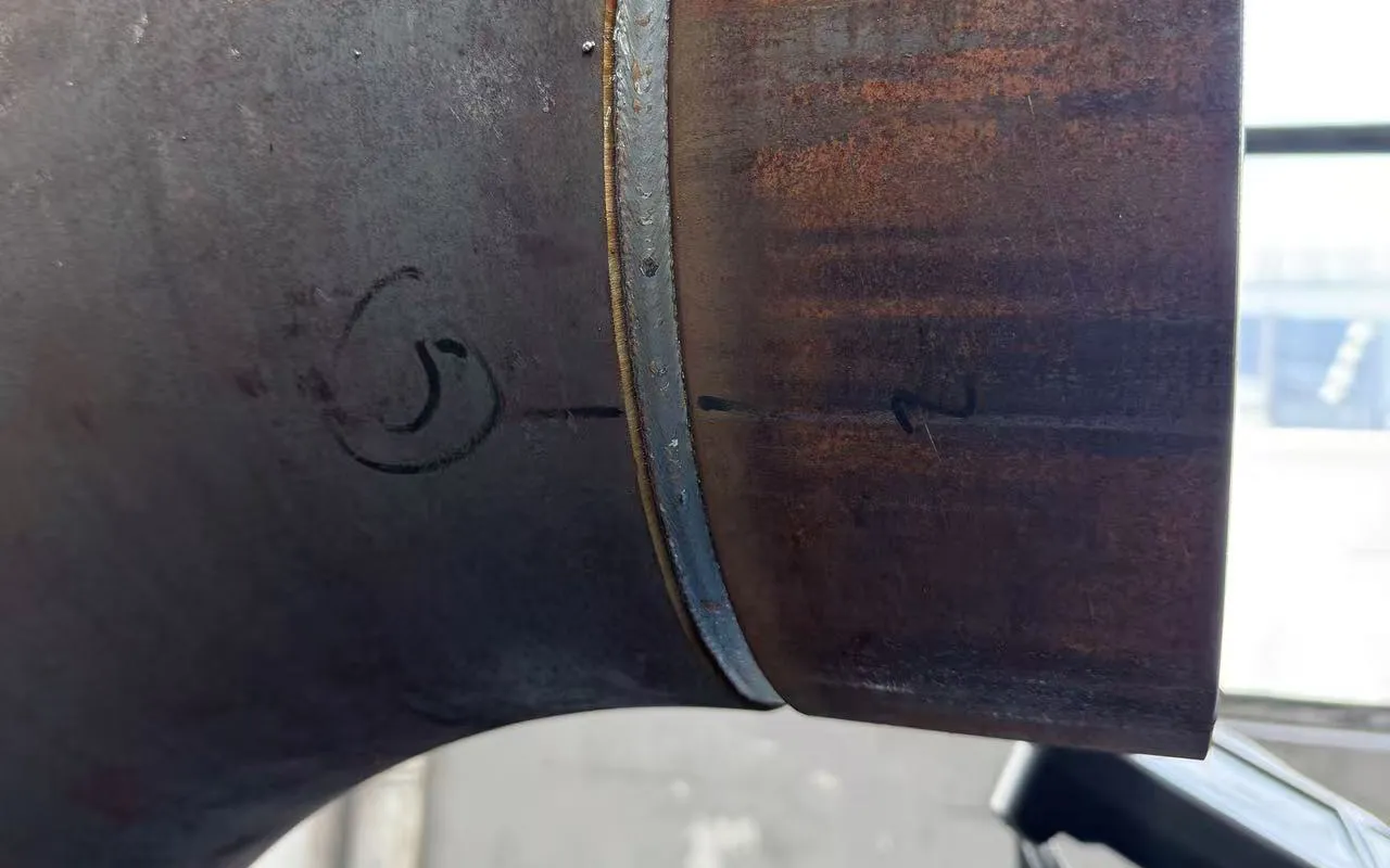
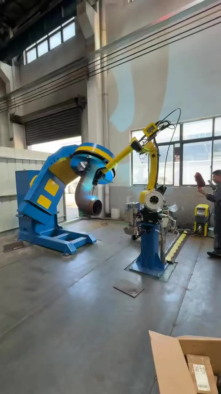
A FANUC robot and an L-type tilting positioner weld the elbow body, flanges and lifting lugs of large-bore, thick-walled 90° elbows in a single clamping.
The production task
Three structures meet in one part. The elbow-to-flange girth seam can run several metres, the wall-thickness difference between flange and shell causes distortion, the lug fillet welds point in different directions, and the flange sealing face must stay free of spatter. Manual welding leaves many restarts, inconsistent beads and cannot keep pace with data center delivery schedules.
The system approach
Haibao integrated a FANUC M-10iD/8L robot, R-30iB controller with arc-welding software, a two-station L-type tilting positioner, a PM500 pulsed MAG power source and a TBI 82W torch. The positioner brings every seam into the flat or gravity position, touch sensing and arc tracking correct deviations during welding, and one-pulse-one-drop transfer keeps spatter low.
- Robot maximum reach
- 2038mm
- Alternating positioner operation
- 2 stations
- Average speed on 16mm carbon steel
- 400mm/min
- Arc time for 9700mm of weld per part
- ≈24.25min
Application
Stable computing starts with cooling water
The heat generated in a large data center is carried away by its cooling water loop. From chillers and plate heat exchangers to CDUs and rack-level equipment, the piping runs at high pressure and high flow, around the clock. The 90° flanged elbow with lifting lugs is one of the most frequent and most process-sensitive fittings: it turns the flow, its flanges seal the joints and its lugs carry it during installation.
- Large-bore, high-flow loops run continuously between the data hall and outdoor cooling
- The flange face is a sealing face: one leak means reworking a whole pipe section
- Slag and spatter inside the pipe contaminate water and block filters and heat exchangers
- A single girth seam can run several metres, which is hard to weld consistently by hand
Workpiece
What makes this part difficult
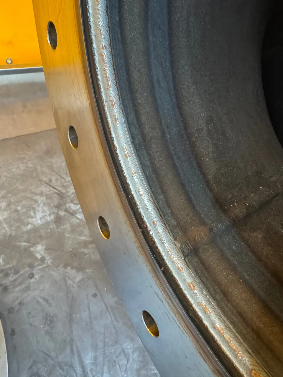
Elbow, flange and lugs: three structures, three joint types and three heat inputs on a single part.
Long, large-bore girth seams
The seam circumference can reach several metres. Manual welding needs repeated restarts and repositioning, so bead quality varies.
Thickness difference and distortion
The flange is much thicker than the shell. Concentrated heat causes angular distortion and flange warping that affect the sealing face.
Scattered lug fillet welds
Lugs sit on both sides of the elbow with welds in different directions, so the part must be turned repeatedly to keep a flat position.
Fit-up gaps and misalignment
Fit-up gap and part repeatability are both within 2mm, but incoming parts always vary. The robot has to find the seam itself.
Protecting the sealing face
Spatter or scratches on the flange face mean grinding or rework on site, so a low-spatter process is mandatory.
Throughput pressure
Data center projects run on tight schedules and large batches. Manual welding cannot supply the output or the labour.
System
One robot. One L-type positioner.
Loading on one side, welding on the other. The positioner moves in coordination with the robot, with a torch cleaning station and safety guarding.
FANUC M-10iD/8L
Robot
2038mm maximum reach, hollow wrist with internal cable routing.
FANUC R-30iB (B-cabinet)
Controller
128MB Flash / 128MB DRAM, DeviceNet and Process I/O.
Touch Sensing / TAST
Arc-welding software
Seam finding, arc tracking, multi-pass welding, arc-voltage correction and coordinated external axes.
L-type tilting positioner
Positioner
Two alternating stations; every weld is completed in a single clamping.
Haibao PM500
Power source
Pulsed MAG power source with SFP one-pulse-one-drop transfer and VR11000 wire feeder.
TBI 82W (Germany)
Torch
100% duty cycle, 400A mixed gas / 500A CO₂, approx. 0.46kg.
Positioner
Every seam in the right position
The girth seams, lug fillets and inner and outer flange welds all face different directions. The positioner turns each one into its most stable welding position.
Tilt axis: level the seam
Tilting brings the girth seam into the flat or gravity position so the weld pool stays stable, which is what produces an even bead.
Rotation axis: continuous seams
The positioner rotates while the robot makes fine corrections, keeping the torch angle constant and avoiding restarts.
Two stations: weld while loading
While station one is welding, the operator loads and clamps the next part on station two. The cell keeps running.
One clamping, every weld
Girth seams, flange fillets and lug welds are completed on one fixture, reducing re-clamping errors and crane time.
Workflow
Eight steps per cycle
The operator follows the work instruction and starts the cycle from the operator box. The robot and positioner do the rest.
01
Load the part
Crane and locate
The elbow is lifted onto the fixture and located by pins and support faces.
02
Clamp
Pneumatic clamping
Clamping cylinders hold the flange face and shell at the same time.
03
Select program
Program number
Choose the program for the part type and confirm torch angle and parameters.
04
Verify
Error proofing
Check part and program match, shielding gas, wire supply and torch cleaning.
05
Start
Coordinated start
Robot and positioner move together into seam finding and arc start.
06
Find seam and root
Touch Sensing
The wire touches reference points to compensate offsets, then the root pass is welded.
07
Fill and cap
TAST tracking
Arc tracking corrects deviations in real time while passes are built up to the cap.
08
Reset and switch
Cycle
The robot returns home and moves to station two while the operator unloads.
Process
The robot finds the seam itself
Girth seams shrink and move with heat input. Seam finding and tracking let the robot correct its path while welding.
Touch Sensing
Seam finding
The wire tip touches two reference points to measure the actual offset and correct the arc-start position, absorbing fit-up variation.
TAST
Arc tracking
During weaving the welding current is monitored and the path adjusted in both directions; the first pass is stored for multi-pass welding.
SFP one pulse, one drop
Pulsed MAG welding
Each pulse transfers one droplet with low heat and a focused arc. Spatter drops sharply and the flange face needs no extra grinding.
Multi-pass
Multi-pass with voltage correction
Heat input is controlled pass by pass to reduce distortion, while arc-voltage sensing corrects stick-out changes for good inter-pass fusion.
Clean unit
Torch cleaning
Reaming, wire cutting and anti-spatter spray share one station and run automatically, supporting eight hours of continuous welding.
Safety
Collision protection
Sensitive collision detection and a torch shock sensor stop the robot instantly; guarding and a signal tower keep people out of the cell.
Site requirements
Four site conditions to confirm first
Robotic welding has clear requirements for power, air and foundations. Confirming them early avoids rework during installation.
Power
- AC 380V ±10%, three-phase
- 50Hz ±1Hz
- Primary earthing of the supply
- Separate feeds for welder and robot
Compressed air
- 0.5–0.7 MPa
- 1-inch outlet
- Dew point -40℃, particles ≤0.1μm
- Oil content ≤0.01 mg/m³
Foundation
- Compacted base, >0.12 MPa
- Concrete floor >23 MPa
- C30 concrete or higher recommended
- Anchor positions for robot and positioner
Environment
- 0–45℃ in operation
- Temperature change 1.1℃/min
- 20%–75% RH, non-condensing
- Below 95% RH for up to one month
Delivery
A process that produces good parts
Drawing review
The design is based on assembly and part drawings and reviewed jointly to confirm robot reach, power source and torch capacity, and fixture fit.
Installation and acceptance
Haibao engineers connect and commission the robot, controller and welder, with acceptance against the technical agreement.
Training
1–2 days of on-site training in programming, operation and maintenance, so that at least three employees can run the cell.
Welding parameter set
Programs for carbon steel and stainless elbows, including root, fill and cap parameters and seam-finding and tracking settings.
Safety
Haibao designs and builds the guarding. Only the operator may enter the cell area while the robot is working.
Packing and transport
Haibao packs and ships the equipment and supports unpacking, inspection and positioning on arrival.
On site
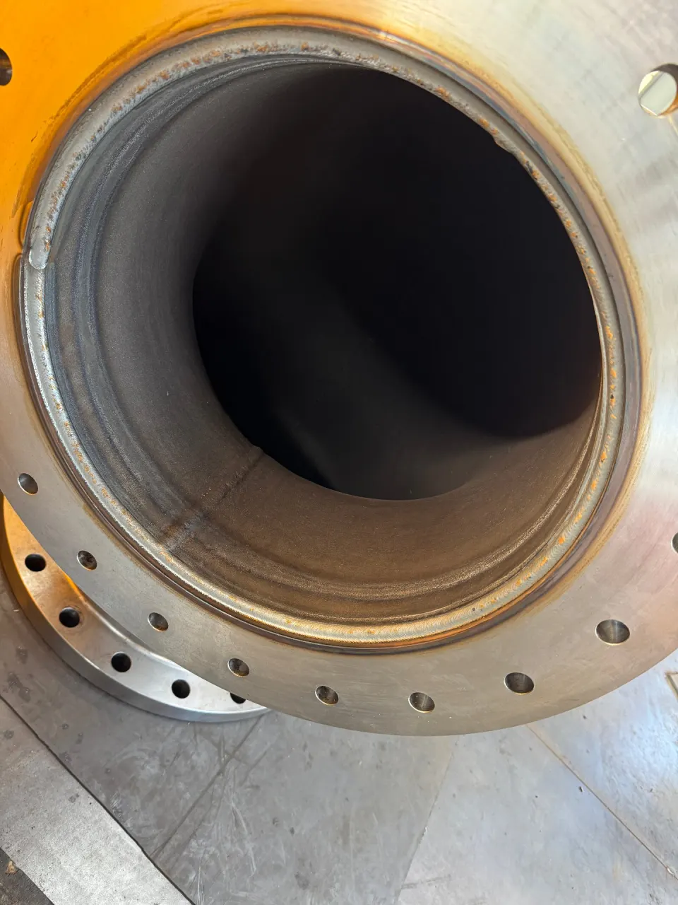
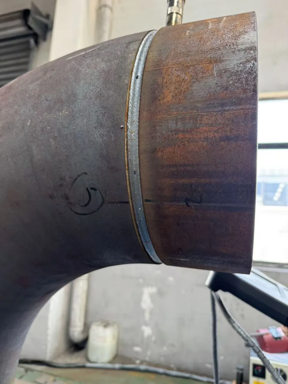
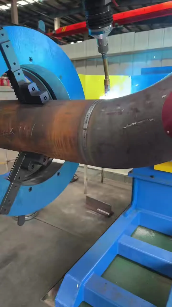
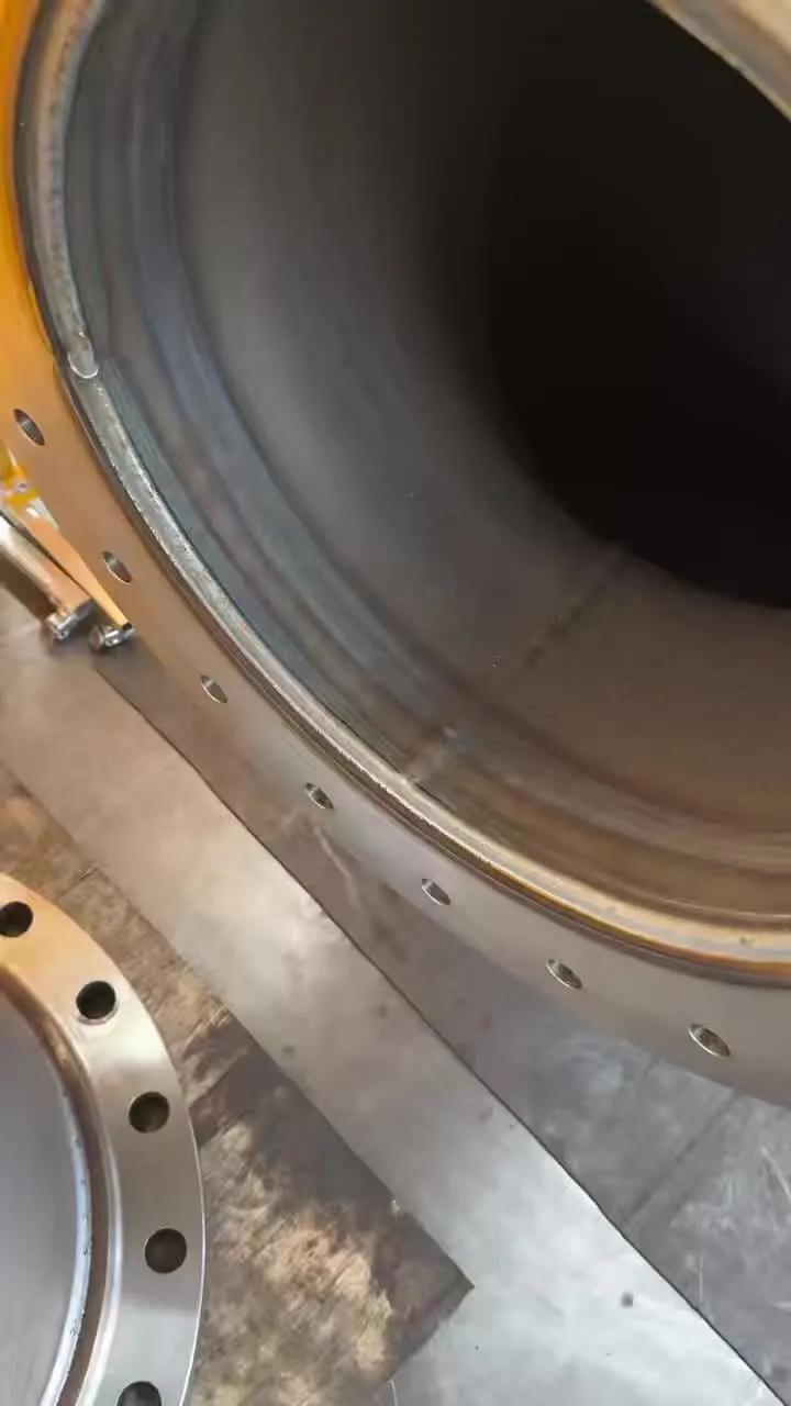
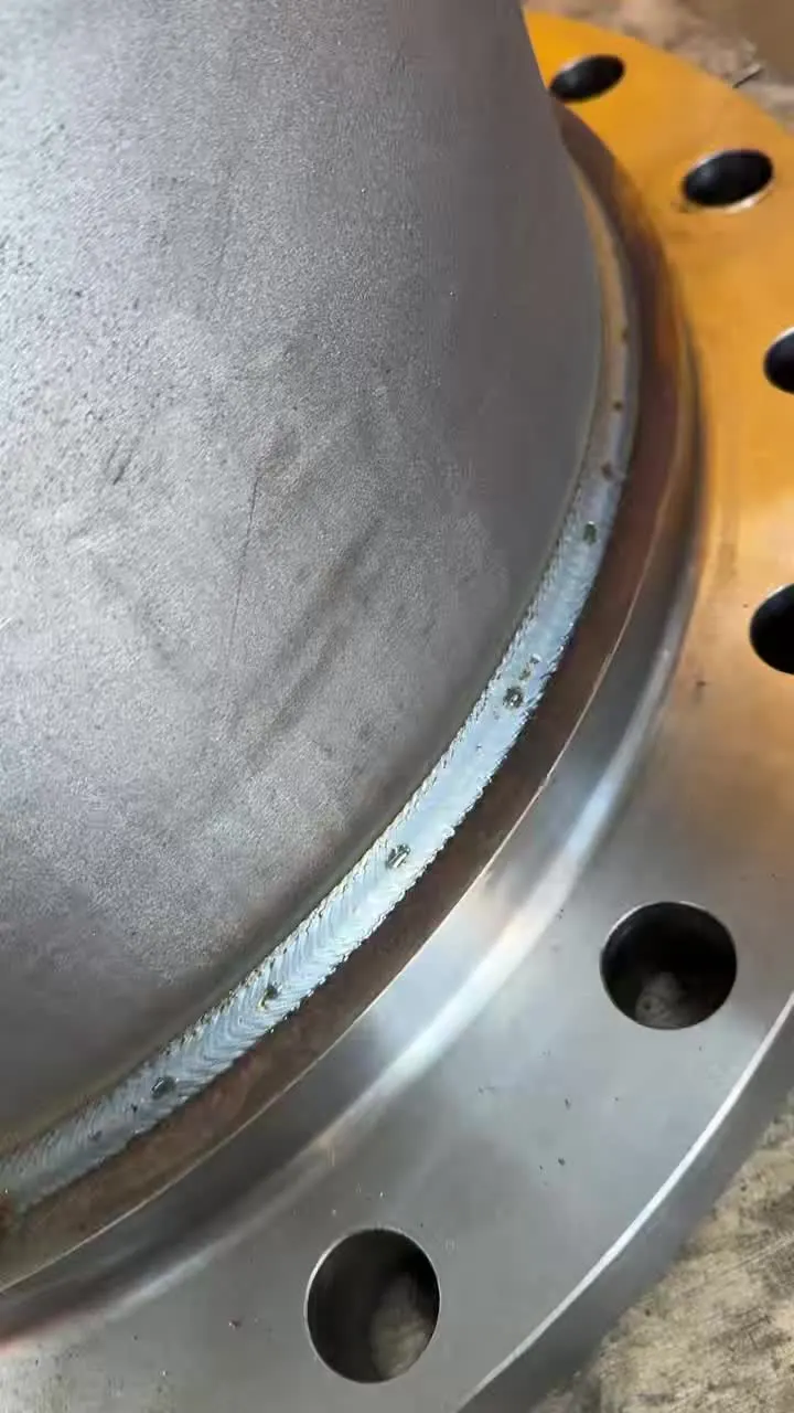
The welds, as they come out
Photos and videos from production at Haibao’s welding cell.
Send us pipe diameter, wall thickness, material, flange standard, lug positions, batch size and delivery schedule. We will propose a positioner, a cell layout and an estimated welding time per part.
Technical data is based on the FANUC robot and L-type positioner technical agreement. The final configuration is defined by the contract; part sizes, weld types and cycle time are calculated from the actual drawings.
What are you working on?
Tell us about your material, workpiece and production needs. Let’s find a practical starting point.
Discuss your project