Jiangsu Xijie New Energy · Nuclear equipment
20kW 3D laser cutting robot delivered to Jiangsu Xijie
Used for 3D hole cutting and bevelling on nuclear pressure vessel shells and tower sections. The system passed acceptance first time; hole-group cutting is about 3 times faster than the previous plasma process, and the holes need no grinding.
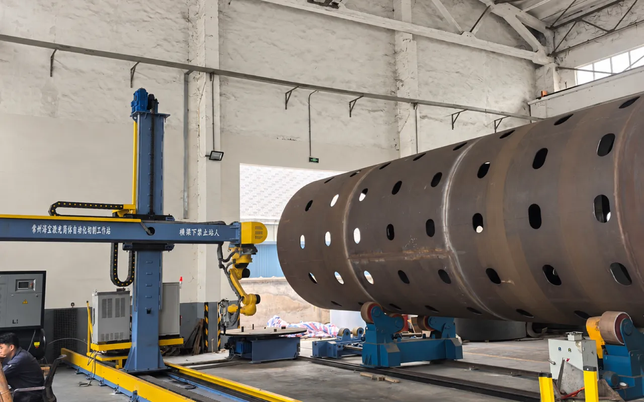 Vertical ram / Z-axis liftSix-axis cutting robotNuclear shell with holes cutBeam nameplate: Haibao laser shell cutting stationFloor rail + travel unitHeavy turning rolls (VFD rotation)
- 1Vertical ram / Z-axis lift
- 2Six-axis cutting robot
- 3Nuclear shell with holes cut
- 4Beam nameplate: Haibao laser shell cutting station
- 5Floor rail + travel unit
- 6Heavy turning rolls (VFD rotation)
The production task
A single shell can need over a hundred holes on its curved surface, from Φ30 to Φ600, positioned relative to girth seams and the shell datum line. The old route of marking out, hand plasma cutting, grinding, dye-penetrant testing and repair left heavy dross and wide heat-affected zones, hole positions varied, and delivery was held up at this last operation.
The system approach
Haibao delivered a gantry-type, six-axis shell hole cutting cell: the gantry handles large-range positioning, the six-axis robot handles 3D orientation, and two-station heavy turning rolls index the shell. Offline programming converts the 3D shell model straight into cutting paths, a full ring of holes is cut in one set-up, and the dross-free cuts go straight to fit-up and welding.
- Fibre laser output
- 20kW
- Hole position accuracy
- ±0.05mm
- Cut squareness, no grinding
- ≥99.5%
- Hole-group throughput vs plasma
- 3×
Customer
Why hole cutting on nuclear shells became the bottleneck
Jiangsu Xijie New Energy Engineering Technology, based in Yixing, Jiangsu, is a national high-tech enterprise making nuclear chemical, nuclear power and defence waste treatment equipment, ASME code products and pressure vessels. Nuclear products demand far higher cut quality, hole tolerances and traceability than ordinary pressure vessels.
- Long cutting and grinding time per shell held up delivery
- Hole quality depended on the operator; rework and inspection costs stayed high
- Frequent hole-type changes meant long marking, set-up and trial cuts
- Nuclear work requires tighter cut quality, tolerances and traceability
Project file
What was delivered
- Customer
- Jiangsu Xijie New Energy Engineering Technology Co., Ltd.
- Delivered
- 2026
- Applications
- Nuclear pressure vessel shells, nuclear tower sections, nuclear waste treatment vessels, large stainless and carbon steel shells
- Capabilities
- 3D hole cutting, intersecting holes, slotted and profiled holes, one-pass bevels, batch hole arrays
- Equipment
- Gantry, six-axis robot, 3D laser cutting head, two-station heavy turning rolls, CNC and offline programming
- Result
- Accepted first time; hole cutting reduced from "cut + grind + re-inspect" to "cut + sample check"
Requirements
Four requirements from the customer
Measurable hole accuracy
Hole centres held within ±0.1mm regardless of shift or operator, with traceable inspection records.
No grinding
No dross or oxide build-up, good squareness, and holes ready for fit-up and welding straight after cutting.
Fast changeovers
Shell diameter, hole type and spacing change often, so paths must come from offline programming with minimal set-up downtime.
Large parts
Shells of Φ1–6m, around 12m long and tens of tonnes must have all hole groups cut in one set-up.
The system
A 3D laser cutting cell built for large shells
The gantry positions, the robot orients and the turning rolls index the shell. Working together, they cut a full ring of holes in one set-up.
Height-following head
As the shell turns, the surface height changes. Height following keeps the nozzle distance constant so the kerf does not widen or fail to cut through.
Fully enclosed cable chains
Fibre, gas, water and control lines move with the beam without repeated sharp bends, which is key to long-term stability of a high-power laser.
No grinding marks
No grinder marks on the shell and no spatter around the holes show that cutting parameters and assist gas are well matched.
Holes driven by the 3D model
Hole positions come from the model, not from marking and manual set-up. Varied diameters, spacing and profiles are parameters in software, with no hardware change.
A full ring in one set-up
The system generates indexing angles and robot poses automatically: the shell turns into position, the head moves in, a ring of holes is cut, then the next angle.
Traceable data
Cutting paths and inspection data are archived to meet nuclear traceability requirements.
Cut quality
Direct evidence of no-grind holes
Four things decide laser cut quality: a clean profile, no dross, square edges and a controlled heat-affected zone.
Laser vs plasma
Clean profile
Slotted holes have smooth end radii, no skew along the long axis, and match the model.
Plasma: heavy dross, needs chipping
No dross
No dross on the lower edge, so no chipping or grinding before the next operation.
Plasma: about 90–95%
Squareness ≥99.5%
The cut face is nearly square with little difference between top and bottom, giving a stable bevel allowance.
Plasma: wider, with oxide layer
Narrow heat-affected zone
High energy density and short exposure limit changes to the base metal, lowering welding risk later.
Specifications
Typical configuration of the delivered system
Shell diameter, length, load and gantry travel can be tailored to the customer’s product range. Cutting thickness depends on material, assist gas, hole size and bevel and is confirmed by process trials.
20kW fibre laser
Laser power
Cuts medium-thick plate in one pass.
3D laser cutting head
Cutting head
Height following with capacitive sensing.
Twin columns + box beam
Gantry
Stress-relieved; X ≤12000mm, Z 2500mm.
Φ1000 – Φ6000mm
Shell range
Length ≤12000mm, load ≤60t.
±0.05mm / ±0.03mm
Accuracy
Positioning / repeatability; hole consistency CPK ≥ 1.33.
Carbon ≤30mm / stainless ≤20mm
Thickness
Oxygen assist for carbon, nitrogen for stainless, subject to trials.
CNC + offline programming
Programming
Imports 3D models.
Optional
Options
Laser edge finding, vision positioning, fume extraction, laser safety fencing.
Delivery
The machine is the carrier; the parameters are the core
The real time on this project went not into installation but into proving the parameter sets for each of the customer’s common materials, thicknesses and hole types, then fixing them as process cards.
01
Requirements and feasibility
Confirm shell range, hole list, accuracy and output targets, then recommend a configuration.
02
Sample cuts and parameter proof
Cut the customer’s actual material to verify quality, squareness and speed, setting a parameter baseline.
03
Build and factory acceptance
Gantry, robot and turning rolls are run together, with accuracy checks and dry runs in the factory.
04
Installation and commissioning
Foundation levelling, rail laying, full-system tuning and test cuts on real shells.
05
Process lock-in and training
Parameter sets fixed, program templates handed over, and training in operation, programming and maintenance.
06
Acceptance and ongoing service
Item-by-item acceptance to the technical agreement, then warranty with remote diagnosis and site response.
FAQ
Laser hole cutting on nuclear shells
How thick can 20kW cut?
About 25–30mm carbon steel with oxygen and 15–20mm stainless with nitrogen. Thicker shells usually combine laser hole cutting and bevel pre-cutting with plasma or machining for the final form. Exact limits are proven by trials and written into the agreement.
Why laser instead of plasma?
Plasma leaves dross, oxide and a wide heat-affected zone, so nuclear shells need grinding and dye-penetrant testing. Laser gives a narrow kerf, small HAZ and square edges, removing the grinding step and improving hole accuracy from millimetres to ±0.05mm.
How is hole accuracy assured?
A rigid twin-column gantry holds stiffness over long travel, the robot sets 3D orientation and the rolls index the shell. Laser edge finding and the shell datum define the work coordinates, and offline programming turns the 3D model into paths.
How large a shell can it handle?
The standard model covers Φ1000–Φ6000mm, up to 12000mm long and 60t. Longer gantry travel and heavier, wider turning rolls can be built for larger parts.
Is grinding still needed?
With matched parameters there is no dross and squareness is ≥99.5%, so holes go straight to welding or fit-up. Only pierce and finish points may need light touch-up per the procedure.
Lead time and service?
About 90–120 days for the standard configuration, including installation, operation and programming training and parameter lock-in. Remote diagnosis and 48-hour site response during warranty.
On site
The system in Jiangsu Xijie’s workshop
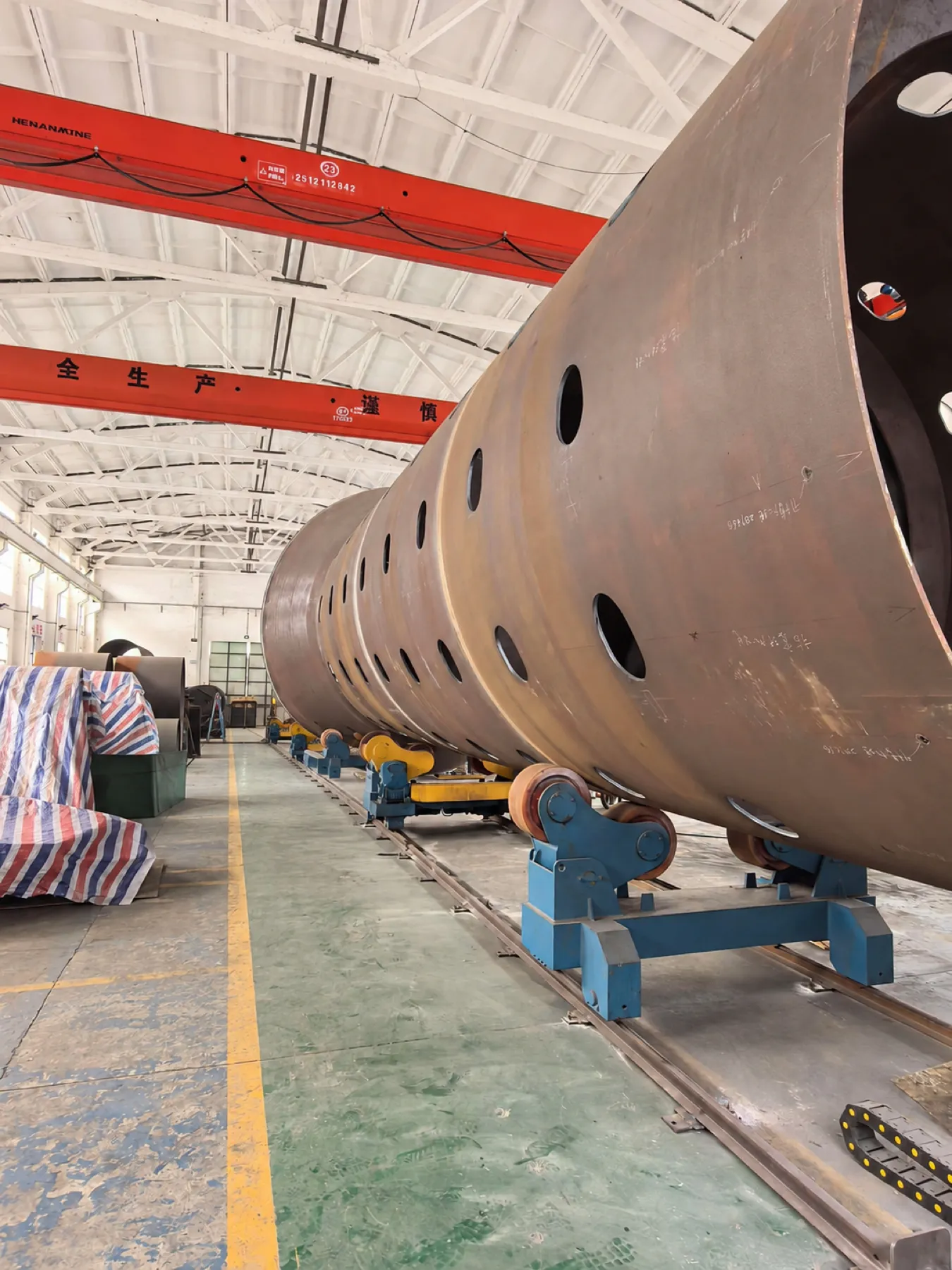
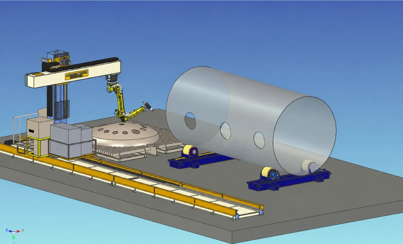
The first two images are 3D layout drawings; the rest are photos from the customer’s workshop.
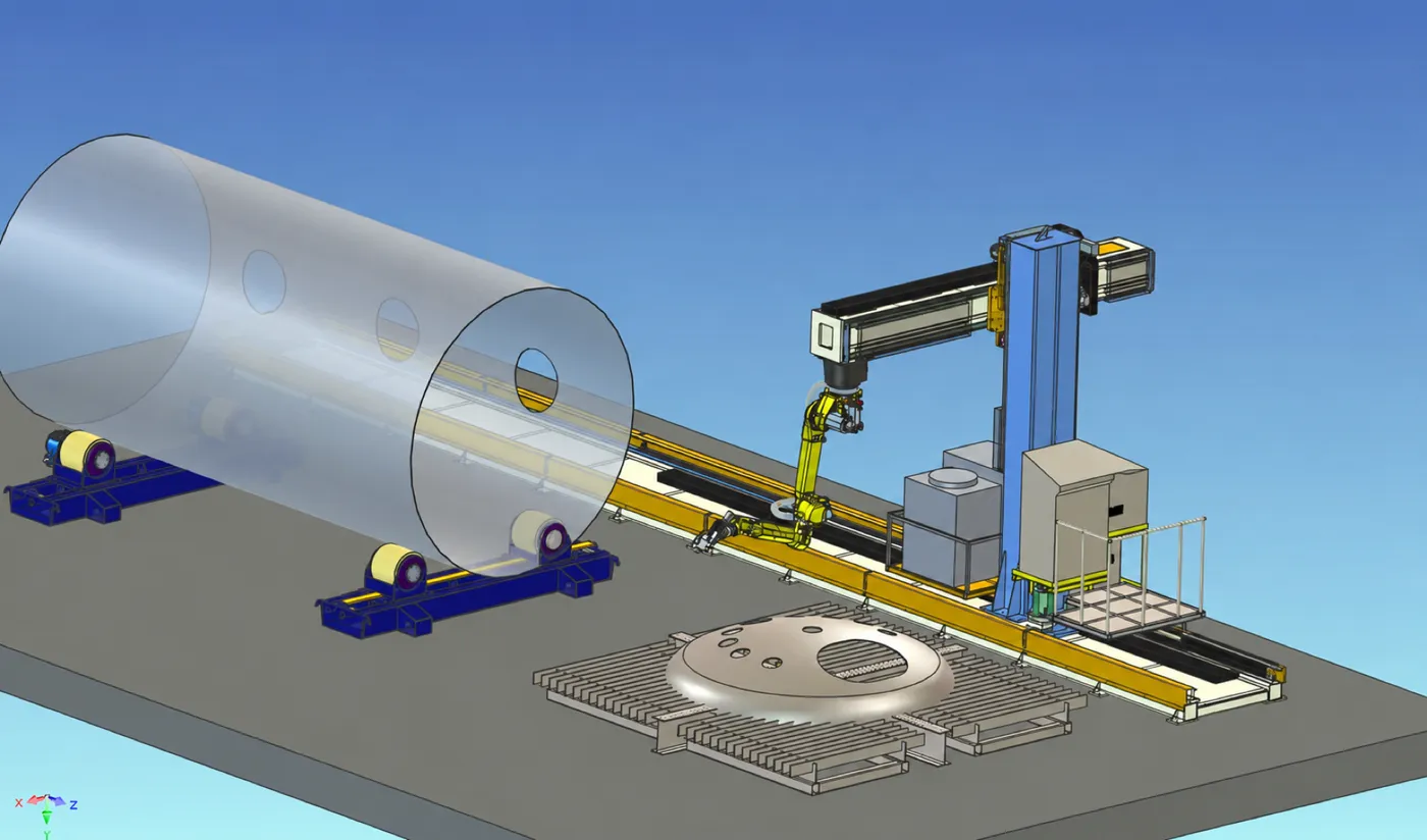 Nuclear pressure vessel shellRigid twin-column gantry beamSix-axis robot, flexible orientationFloor-rail travelTwo-station turning rolls (shell rotation)20kW 3D laser cutting headGrid cutting table
- 1Nuclear pressure vessel shell
- 2Rigid twin-column gantry beam
- 3Six-axis robot, flexible orientation
- 4Floor-rail travel
- 5Two-station turning rolls (shell rotation)
- 620kW 3D laser cutting head
- 7Grid cutting table
 Gantry + cantilever beam3D hole group on the shellSix-axis robotLaser head, square piercingHeavy-duty turning rollsLong-stroke precision rail
- 1Gantry + cantilever beam
- 23D hole group on the shell
- 3Six-axis robot
- 4Laser head, square piercing
- 5Heavy-duty turning rolls
- 6Long-stroke precision rail
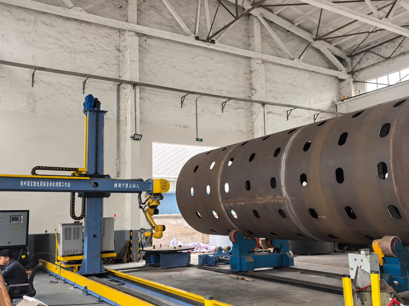 Vertical ram / Z-axis liftSix-axis cutting robotNuclear shell with holes cutBeam nameplate: Haibao laser shell cutting stationFloor rail + travel unitHeavy turning rolls (VFD rotation)
- 1Vertical ram / Z-axis lift
- 2Six-axis cutting robot
- 3Nuclear shell with holes cut
- 4Beam nameplate: Haibao laser shell cutting station
- 5Floor rail + travel unit
- 6Heavy turning rolls (VFD rotation)
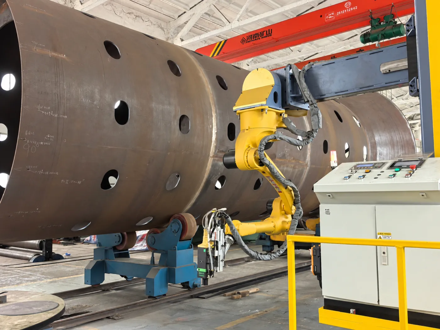 Cut holes, no drossHole group, even spacingGantry beam / cable chainSix-axis robot armIntegrated cabinet / control panelTurning rolls support and rotate the shellLaser head (height following)
- 1Cut holes, no dross
- 2Hole group, even spacing
- 3Gantry beam / cable chain
- 4Six-axis robot arm
- 5Integrated cabinet / control panel
- 6Turning rolls support and rotate the shell
- 7Laser head (height following)
Overhead crane for liftingHole bore, no dross insideLarge shell, assembled in sectionsHole group: varied size and spacingTurning rolls + travel track- 1Overhead crane for lifting
- 2Hole bore, no dross inside
- 3Large shell, assembled in sections
- 4Hole group: varied size and spacing
- 5Turning rolls + travel track
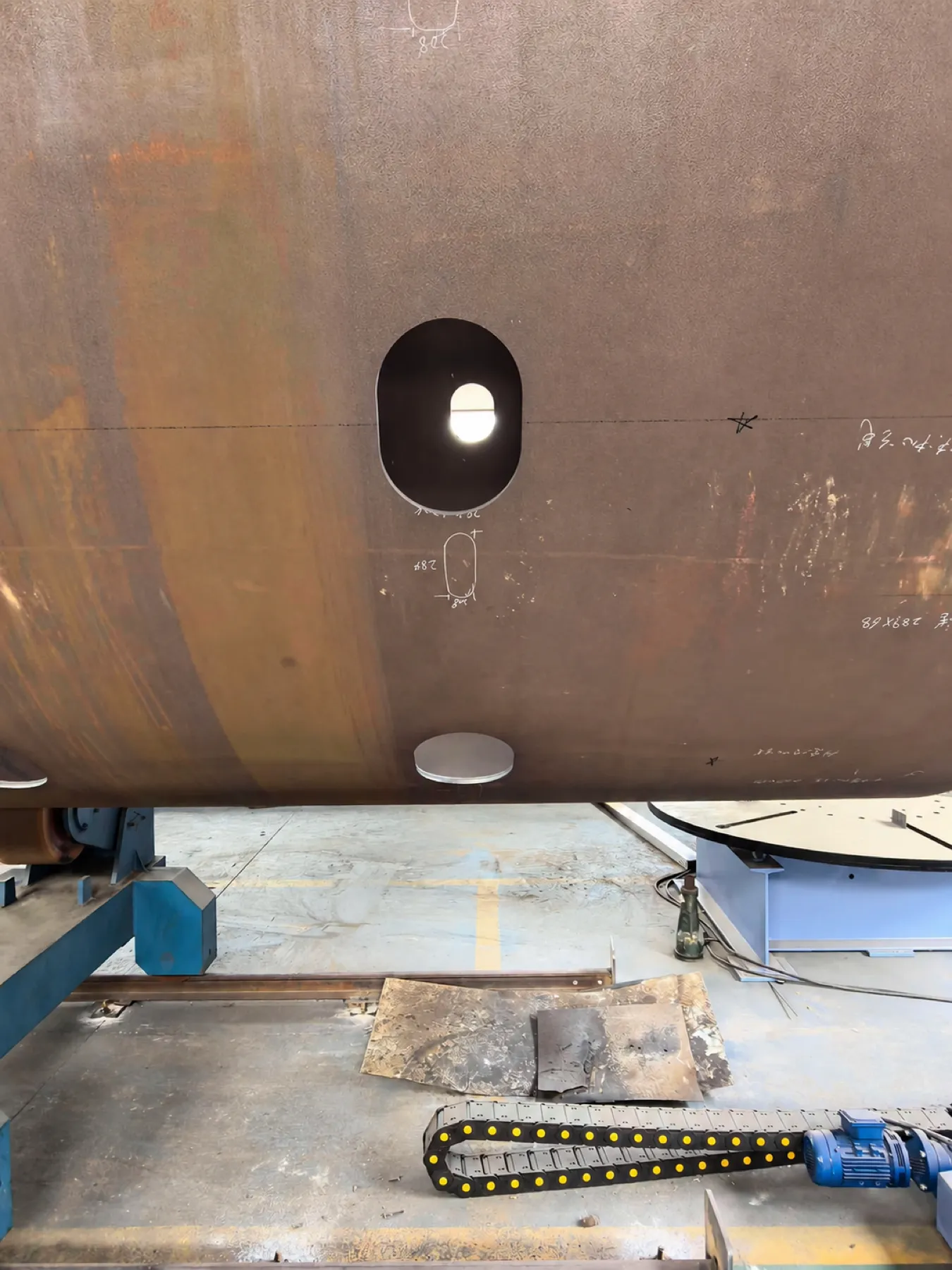 Slotted hole profileSquare cut, no regrindingSmooth edge, no drossLayout line / alignment markCoaxial locating hole
- 1Slotted hole profile
- 2Square cut, no regrinding
- 3Smooth edge, no dross
- 4Layout line / alignment mark
- 5Coaxial locating hole
Customer feedback
What the customer says
Commissioning went smoothly after delivery. Speed and consistency on shell hole groups are clearly better than our old plasma-plus-grinding process, and the holes hardly need any rework. Haibao’s engineers supported production on site for over two weeks and we worked out the parameters together, so now we can handle changeovers ourselves.
Can your shells be laser cut? Send us the material, thickness, hole sizes and hole list, and within 3 working days we will assess feasibility, recommend a configuration and estimate cycle time.
Specifications are the typical configuration of the delivered system; the technical agreement and factory acceptance report govern. Laser vs plasma comparisons come from measurements before and after delivery on this project and vary with material, thickness and parameters.
What are you working on?
Tell us about your material, workpiece and production needs. Let’s find a practical starting point.
Discuss your project